Founded 1998, HYDROKOMP designs, manufactures and distributes hydraulic components, coupling systems and clamping technology for mechanical engineering, fixture construction, tooling and many other branches of industry also for different operating conditions.
Ball coupling elements
Description
Ball coupling elements from HYDROKOMP are manufactured from stainless materials.This enables the elements to be used for all fluids and gases, that are non-aggressive.
The ball coupling elements should be used in situations with limited spaces and low coupling intervals. In case of higher coupling intervals our standard coupling elements (datasheet 100-3) should be used, because they have no leakage during the coupling action.
The coupling action must be performed while the system is not under pressure, as the system seal must be compressed before pressurizing the canals.
Important to note is that the single elements can be pressurized, for instance in a closed circuit, but not during the coupling action.
-
stainless materials
-
space-saving installation
-
sealed with ball
-
transmission of non-aggressive liquid and gaseous mediums
-
flat profile
-
close to no contamination in the system because of system seal
-
the frontal contour enables easy cleaning, failures due to contamination are minimal
Operating conditions:
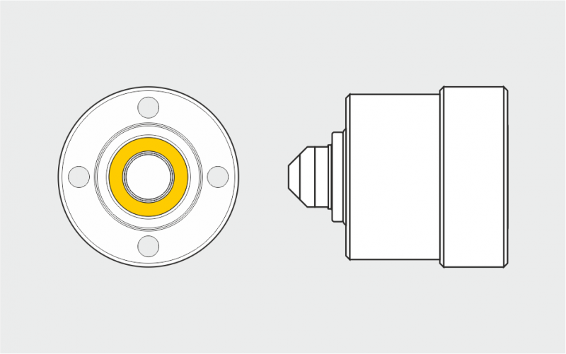
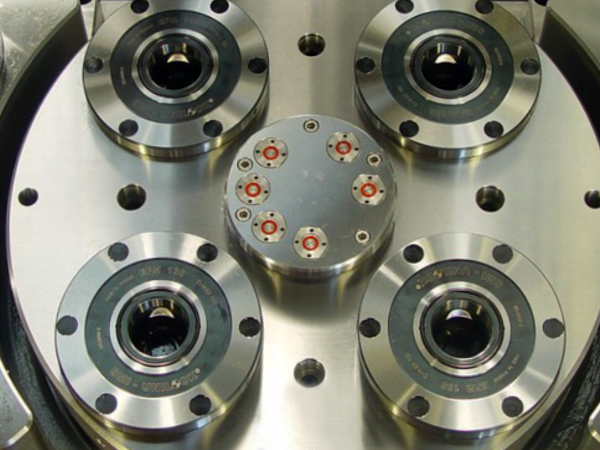
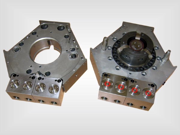
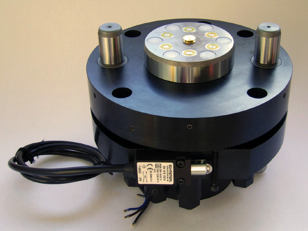
Coupling nipple and coupling mechanism must face each other coaxially before the coupling process starts. The base plates of both elements must be guided about 0-1mm before the contact of the two balls. The radial positioning tolerance shall not be exceeded.
The coupling force between coupling nipple and coupling mechanism, resulting from the hydraulic or fluid pressure, has to be compensated positively from the outside.
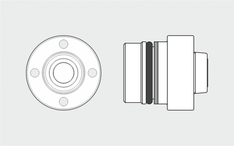
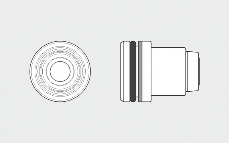
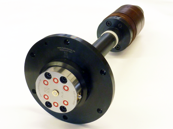
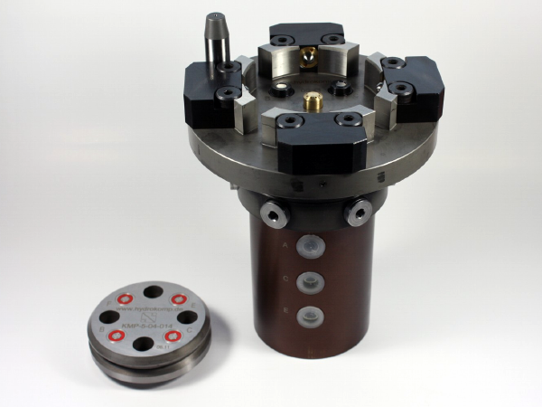
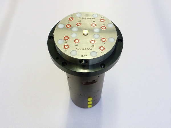
The axially placed O-ring acting as a front seal, protects the system from contamination. Keeping the face surfaces in a clean state is critical. Water or air can be used for cleaning.
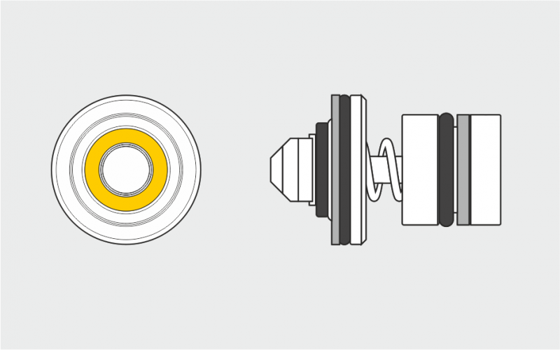
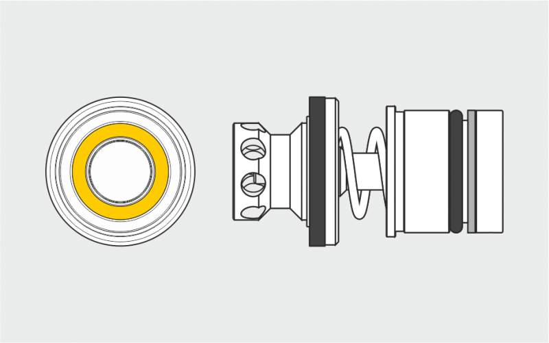
The single elements are sealed with a POM insert, which holds the ball in place. Moreover, an O-ring has to be placed on the bottom of the bore to ensure fluid tightness. The surface quality of the bore is a key factor for the elements to be leak free.
Application Example
Data sheet 100-7
Nominal diameter:
3
Operating pressure:
pmax. 350 bar
Flow:
5 l/Minute
Coupling stroke:
2 mm
Coupling force:
Min. 83,6 N (at 0 bar)
Design:
threaded body design
Operating method:
depressurized coupling
Medium:
fluid or gaseous media
Data sheet (PDF):
Design:
Ball coupling mechanism Screw-in design
Operating method
- depressurized coupling
Manual coupling systems
Description
Manual coupling systems are applied with machine tools that operate with hydraulic fixtures but do not have a standard equipment of a hydraulic interface for oil supply to the fixture pallet. The operating personnel take care of coupling and decoupling. In contrast to quick-locking couplings, manual couplings do not bear the danger of mixing up pressure line and tank line. Also, the coupling process is made much faster. After clamping the workpiece it is easy to unclamp the system without effort by the use of a hydraulically piloted check valve. Also the system pressure remains. To unclamp the system the T-port must be pressurized. At the single-acting coupling system the ball valve takes this feature.
Required safety elements are already integrated. These include one hydraulic accumulator, one check valve and one pressure relief valve which protects the hydraulic accumulator from a pressure rise over 10%. The coupling unit can be equipped with two different hydraulic accumulators. HYDROKOMP recommend the accumulator with 13 cm³ nominal volume up to an oil volume of approx. 100 cm³ in the fixture. When the required oil volume is larger, the hydraulic accumulator with 40 cm³ nominal volume should be applied. The hydraulic accumulators are subject to technical rules for pressure vessels. As standard the manual coupling systems are equipped with manifold and G1/4 threaded ports for oil supply. All flange-on surfaces have O-ring counter-bores on the bottom and on the rear side, which also allow oil supply without pipes through drilled ducts.
-
versatile mounting options
-
safety elements are integrated
-
no mixing up of pressure line and tank line
-
quick and easy coupling
-
system pressure remains during coupling
-
standard systems and special designs available
Safety information:
A safety holder with an inductive proximity switch is optional available for the double-acting coupling system. The safety retainer keeps the coupling mechanism board in the decoupled state into a parking station. Through the integrated proximity switch the safety holder can be directly connected with the machine control. With that, the pallet transport is only permitted in decoupled state. With the help of a equalizer valve in the coupling nipple of the T-port the pressure rise is limited to about 5 bar in decoupled state, eg. when a leakage in the system occurs. For coupling and uncoupling of the coupling nipple unit and the coupling mechanism board both hydraulic lines must be depressurized by the hydraulic valves.
Application examples
Data sheet 100-2
Nominal diameter:
5 (coupling elements)
Operating pressure:
pmax. 500 bar
Design:
coupling unit with lever or ball valve
Operating method:
single-acting or double-acting
Oil supply:
threaded port G1/4 or manifold with O-ring
Hydr. accumulator:
13 cm³ or 40 cm³
Data sheet (PDF):
System components:
Coupling nipple unit (MKN)
1. Coupling nipple with pressure relief valve
2. Hydraulic accumulator 13 cm³ or 40 cm³ (optionally)
3. Hydraulically operated check valve Qmax. = 20l/min
4. Pressure gauge up to 600 bar
5. Pressure relief valve, opening pressure 425 bar
6. Coupling nipple for depressurized coupling
Coupling mechanism board (MKM)
Coupling mechanism board, which locks both components for pressure transfer. Both tension rods are inserted into the bayonet catch. Then the levers are turned to the side by 90°. Through two integrated drafts the tension rods are shortened and the coupling process is executed. The locking stroke is 5 mm.
1. Coupling mechanisms
2. Levers for locking the modules
Safety holder (MKS)
Safety holder with inductive proximity switch and plug (cable length 3 m). The safety holder takes up the uncoupled coupling board into a parking station.
Through the integrated proximity switch the safety holder can be directly connected to the machine control. So, the pallet transport is only permitted in uncoupled state.
1. Hole with counterbore DIN 74 - F4
2. Inductive proximity switch
3. Plug with cable
Coupling unit with ball valve (MK)
The coupling unit can be connected optional at factory
by flange-bottom, flange-rear or rear threaded port.
1. Hydraulic accumulator 13 cm³ or 40 cm³ (optionally)
2. Pressure gauge up to 600 bar
3. Pressure relief valve, opening pressure 425 bar
4. Flat face plug with dust cover
5. Ball valve
6. Port Ø5 mm, O-ring or screw plug
7. Cap head screws DIN 916, M6x60 (not included)
Coupling elements
Coupling mechanisms
built-in and threaded body designs
Coupling nipples
built-in and threaded body designs
Screw-in tools
for coupling elements
(Accessory)
Mounting tools
for the replacement
of the system seal at
coupling mechanisms
(Accessory)
Description
Coupling elements of HYDROKOMP are made of stainless materials. This enables the elements to be used for all fluids and gases that are not aggressive. Special designs eg. for water steam or other media are available on request. HYDROKOMP offers coupling elements for two different operating modes depressurized coupling or pressurized coupling. The elements for depressurized coupling can be coupled pressurized up to 25 bar, if the specified volume flow is not be exceeded. When using higher operating pressure there ockures a risk of demaging the soft seal in the check valve as the result of high flow velocities of the fluid. This means for coupling of air up to 10 bar there should be always used the coupling elements for depressurized coupling. This also applies when the coupling process is initiated pressurized. The elements which can be coupled pressurized may be coupled up to the maximum specified operating pressure on one side and / or on both sides.
The built-in elements are particularly suitable for installation in plates of multiple coupling systems. Threaded body elements can be directly scewed into the fixture body, for example of a tool change system. There, they are ideal suitable as an interface for medium transfer.
-
stainless materials and replaceable system seals for long service life
-
ideal for space-saving installation in individual receiving housings
-
transmission of liquid and gaseous mediums and vacuum
-
pressurized or depressurized coupling
-
various with four nominal diameters
-
standard elements and special designs available
-
HT-Variant operating temperature up to 200°C NEU!
Operating conditions:
Coupling nipple and coupling mechanism must face coaxially each other before the coupling process. The base plates of both elements must be guided about 2 to 3 mm before contact of the sealing surfaces within the radial positioning tolerance. The coupling force between coupling nipple and coupling mechanism resulting from hydraulic pressure according to the formula has to be compensated positively from the outside.
The axially acting front seal areas must be protected from contamination. Good results can be archieved by rinsing and following blowing-off with compressed air. The sealing of the mechanism is done in the drill base of the mounting hole. The required surface quality in the drawing has to be kept.
B = status coupled
C = coupling nipple
D = coupling mechanism
E = coupling stroke
F = axial position tolerance
Application examples
Single coupling system
with cleaning nozzle, (ND 5) depressurized coupling, housing
according to customer's requirements
Coupling nipple plate
with coupling nipple
threaded-body design
Coupling mechanism plate
with cleaning nozzle,
coupling mechanism
built-in design
Single coupling system
(ND 3) depressurized coupling, housing according to customer's requirements
Coupling mechanism plate
with coupling mechanism
threaded-body design
Coupling nipple plate
with coupling nipple
threaded-body design
Multiple coupling system
The built-in coupling elements are particularly suitable for installation in plates for multiple clamping systems
In these systems different coupling elements can be combined. Also rotary couplings can be integrated as well as
additional functions eg. hydro mechanical locking and cleaning nozzle etc.
Data sheet 100-3
Nominal diameter:
3, 5, 8 and 12
Operating pressure:
pmax. 250 - 500 bar
Flowrate:
8, 12, 25 and 50 l/minute
Coupling stroke:
4,5 , 7, 10 mm
Coupling force:
min. 94, 98, 169 N (at 0 bar)
Design:
built-in and threaded body elements
Operating method:
for pressurized or depressurized coupling
Medium:
fluid or gaseous media or vaccum
Data sheet (PDF):
Designs:
Coupling mechanism threaded body design
Operating method:
- pressurized coupling
(system seal yellow)
- depressurized coupling
(system seal red)
Coupling nipple threaded body design
Operating method:
- pressurized coupling
- depressurized coupling
Multiple coupling systems
Description
Multiple coupling systems are predominantly used in machine tools, where they serve as the interface for media transmission between the fixture pallet and the loading and unloading station, or the machining station. Applications have been successfully carried out in other areas of engineering, such as handling technology, robotics and in the construction of moulds and dies.
The design of the coupling systems is based on the built-in coupling elements. These are integrated into a common plate in a very compact and functional manner. We provide standardized subassemblies or design and manufacture customer specific coupling systems.
-
different coupling elements can be combined
-
combinable with rotary couplings
-
additional functions can be integrated
-
depressurized or pressurized coupling
-
varied with four nominal diameters
-
transfer of liquid, gaseous media and vacuum
Functioning:
The coupling elements required for the transmission of media are built into common base plates. The coupling mechanism plates are fitted in the operating and machining station, and the coupling nipple plates in the fixture pallets. Depending on the design, various additional functions can be integrated into the coupling plates.
The spring-loaded blast nozzle built into the coupling mechanism plate can be designed in such a way that the jet of air in the coupled state can, for example, be passed on for system monitoring of the workpieces. In order to avoid the clamping of the device pallet and the associated absorption of coupling forces, the coupling systems can be equipped with a self-locking system that saves on additional, expensive clamping elements in the operating station.
The coupling elements themselves are all made of stainless materials. This means that not only hydraulic fluids but also air or vacuum can be transmitted with no difficulty. Coupling elements of different nominal diameters can be combined in a multiple coupling system. Combinations with rotary couplings in the operating station permit the fixture pallet to be turned through 360°, thus providing easy access to the fixture.
Operating conditions:
The coupling elements can be coupled either only when depressurized or when pressurized up to maximum operating pressure, whichever is chosen. If systems are used that can be coupled under pressure, it is, for example, possible to effect a pressure change to the clamping pressure during machining, which is not possible when pilot-controlled check valves are used in the clamping line.
Application examples
Data sheet 100-4