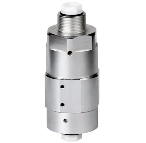
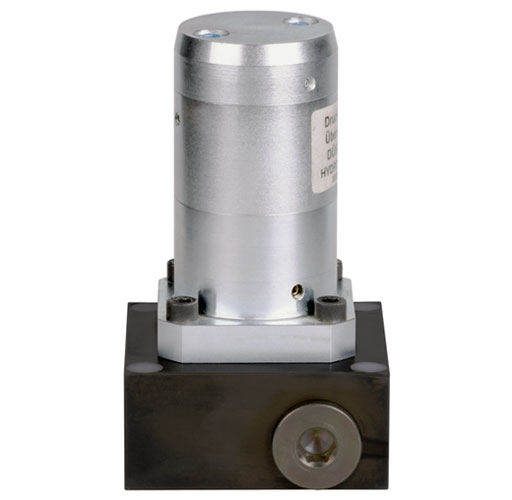
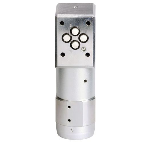
Hydraulic intensifiers, cylindrical
Description
Hydraulic intensifiers increase hydraulic pressure by a fixed ratio. With this method it is possible, eg. to use a low-pressure machine hydraulic system for consumers that can profitably benefit from a pressure that is multiple higher. The intensification is achieved by means of a fixed ratio between two pistons surface areas. That means that the secondary pressure can be controlled by means
of the input pressure.
A non-return by-pass valve is available for the rapid filling of the hydraulic consumer. Intensification starts automatically at approx. 20 bar. The oscillating pump action starts automatically when there is a flow rate through the intensifier. The intensification ends automatically when the consumer no longer requires a flow rate and the high pressure has been achieved. The flow rate on the high pressure side depends on the attainable high pressure. The more highly attained high pressure, the smaller the flow rate.
Operating conditions:
We recommend the use of a hydraulic filter with a filter mesh of max. 10 µm to garantee optimal functioning. As a result of structural design of this intensifier there is internal leakage, which is automatically drained off by means of the T-connection. When consumers are uncoupled, it is recommended that an external pilot operated check valve is installed between the intensifier and the consumer. This can be activated to open the T-line.
-
low-wear design
-
various connection options
-
fast, low-loss pressure transmission
-
integrated valve and filter functions possible
Data sheet 430-2
Connection:
G1/4 threaded port, manifold connection with O-ring or CETOP NG 6
Operating method:
hydraulic-hydraulic
Operating temp.:
from -40 °C up to +120° C
Medium:
hydraulic oil up to max. HLP 40, HFC fluid with min. 5% glycol content
Data sheet (PDF):
Designs:
Hydraulic intensifier with G1/4 threaded port:
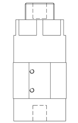
Variants with intensification ratio
1,5 : 1
2,0 : 1
3,4 : 1
4,0 : 1
5,0 : 1
max. volume flow high pressure, start - end
0,8 - 0,2
2,2 - 0,5
1,8 - 0,4
1,4 - 0,3
max. operating pressure inlet, low pressure
160 / 200 bar
max. operating pressure outlet, high pressure
300 / 400 / 680 / 800 bar
Hydraulic intensifier for manifold connection with O-ring, without/with filter plate:
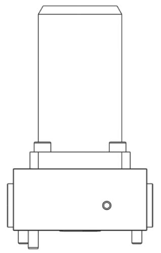
Variants with intensification ratio
2,0 : 1
3,4 : 1
4,0 : 1
5,0 : 1
7,0 : 1
max. volume flow high pressure, start - end
0,8 - 0,2
2,2 - 0,5
1,8 - 0,4
1,4 - 0,3
1,1 - 0,2
max. operating pressure inlet, low pressure
100 / 140 / 175 / 200 bar
max. operating pressure outlet, high pressure
400 / 680 / 700 bar
Hydraulic intensifier with CETOP NG 6 ports:
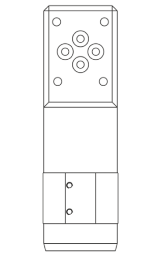
Variants with intensification ratio
1,5 : 1
2,0 : 1
3,4 : 1
4,0 : 1
5,0 : 1
7,0 : 1
9,0 : 1
max. volume flow, high pressure, start - end
0,8 - 0,2
2,2 - 0,5
1,8 - 0,4
1,4 - 0,3
1,1 - 0,2
0,7 - 0,1
max. operating pressure, inlet low pressure
56 / 71 / 100 / 125 / 147 / 200 bar
max. operating pressure, outlet high pressure
300 / 400 / 500 bar


