Hydraulic accumulators
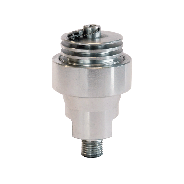
Hydraulic accumulator 13 cm³
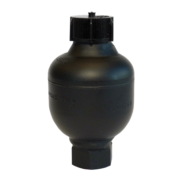
Hydraulic accumulator 40 cm³

Hydraulic accumulator 75 cm³
Description
When using hydraulic clamping systems, internal leaks and volume changes (eg. because of temperature fluctuations) must be balanced. These tasks are performed by the hydraulic accumulator. In intermittent applications, the attached pressure generator fills the hydraulic accumulator during the interruptions. As a result, a short-term high volume flow is achieved, which can be used, as required, to reduce power at the pressure generator. As volume storage, the hydraulic accumulators are also suitable as a source of pressure oil upon failure of the pressure oil supply at the hydraulic pump. When using hydraulic accumulators, the system must be equipped with additional security elements (see safety information). Only qualified personnel may work on the hydraulic accumulator.
Applications:
Balancing internal system leaks
In hydraulic clamping systems, the pressure generator usually operates in off mode. A pressure switch thereby controls the switching operations of the drive motor. If elements that cause a leak due to their construction are connected to the system for example a rotary valve coupling, this causes frequent switching. The hydraulic accumulator substantially reduces the on and off cycles of the drive motor, thus saving energy and reducing wear and tear.
Balancing volume changes
In uncoupled clamping systems, temperature fluctuations may arise. These will inevitably lead to substantial changes in the clamping pressure (± 10 bar at ± 1° C). The installation of a hydraulic accumulator in the system equalises volume, thus preventing undesirable fluctuations in pressure.
-
available in three standard sizes
-
can be mounted in any position
-
discharge of hydraulic components for pressure fluctuations/surges
-
helps to conserve energy
-
reduces wear
Functioning:
The membrane is pressurized with nitrogen. The integrated valve plate closes the opening of the oil inlet, thus preventing damage to the membrane. At minimal operating pressure, a small amount of pressure oil must remain in the vessel so that the membrane does
not close during discharge due to the pressure on the valve plate; p0 must therefore always be set lower than p1. The stored amount of liquid corresponds to the volume change ΔV between the position at minimum and maximum operating pressure.
Safety instructions:
In Germany, hydraulic accumulators are subject to the rules and regulations of the TRB (Technische Regeln Druckbehälter /
technical rules for pressure vessels). Accordingly, the following supplementary equipment is required when using hydraulic accumulators:
- pressure gauge
- relief device
- pressure relief valve
- shut-off valve (optional)
- test pressure gauge connection
Outside of Germany, the national rules and regulations on the use of pressure vessels of the respective country apply.
Application example
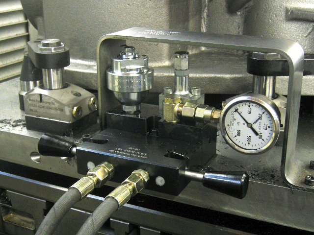
Clamping fixture in a processing palette equipped with swing clamp cylinders. The hydraulic accumulator with a nominal
value of 40 cm³ was installed in a manual coupling system. The pressure oil is supplied via the coupling mechanism board.
In addition to the integrated check valve, the coupling system includes all other safeguards required for the operation
of the hydraulic accumulator.
Pressure gauge:
installed in the supply line of the clamping system to monitor the actual pressure
Pressure relief valve:
Function of the relief device, protects the hydraulic accumulator from a pressure increase of more than 10% of the maximum operating pressure.
Data sheet 600-20
Operating pressure:
pmax. from 50 bar up to 500 bar
Nominal value:
13, 40 and 75 cm³
Preload pressure:
from 10 bar up to 200 bar
Connection:
G1/4 resp. G1/2 or M14x1,5
Volume stored:
from 8,6 cm³ up to 70 cm³
Data sheet (PDF):
Accumulator designs:
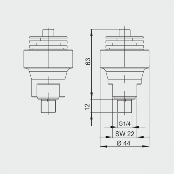
Hydraulic accumulator 13 cm³
Operating pressure: pmax. 500 bar
Preload pressure: 20, 80, 100 or 200 bar
Volume stored: 8,6 / 9,2 / 9,8 cm³
Thread: G1/4
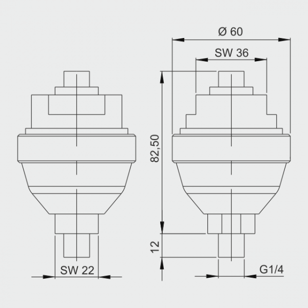
Hydraulic accumulator 40 cm³
Operating pressure: pmax. 400 bar
Preload pressure: 100 bar
Volume stored: 28,8 cm³
Thread: G1/4
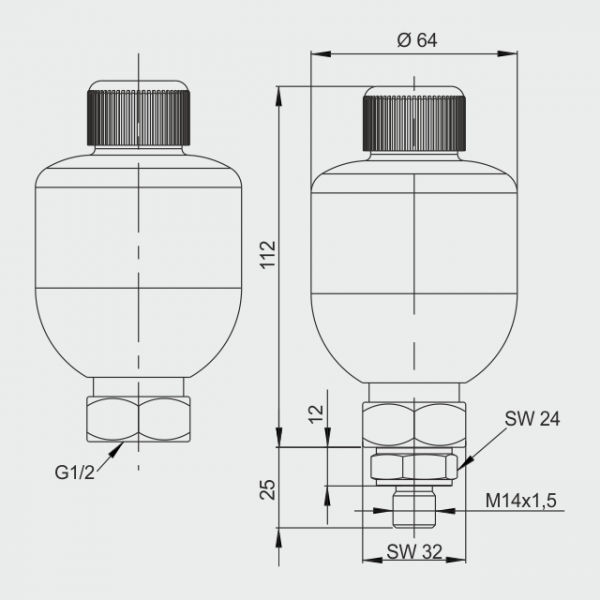
Hydraulic accumulator 75 cm³
Operating pressure: pmax. 50 or 250 bar
Preload pressure: 10, 40, or 100 bar
Volume stored: 45 / 62 / 70 cm³
Thread: G1/2 or M14x1,5
Product configurator:
- generate an order number
- request a quote
- download of 3D models