Hero_Tablet-Mobile_100-2 Manual coupling systems

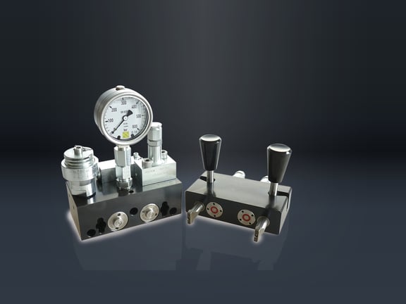
100-2 Manual coupling systems for manual operation, single-acting or double-acting, pmax = 500 bar

Manual coupling systems are used for machine tools that work with hydraulic devices but are not equipped as standard with a hydraulic interface for supplying pressurized oil to the fixture pallet. Coupling and uncoupling is carried out by the operating personnel.

Configure Data sheet

Info

In contrast to quick-release couplings, there is no risk of confusion between the pressure line and tank line with manual couplings. The coupling process is also faster. By using a hydraulically releasable non-return valve, the coupling can be easily disconnected after the clamping process has been completed without the need for force and the system pressure is maintained. To release the pressure, the T-connection is pressurized. In the single-acting version, the ball valve performs this function.

The necessary safety elements are already installed. These are a hydraulic accumulator, a non-return valve and a pressure relief valve that protects the hydraulic accumulator from a pressure increase of more than 10%. The coupling nipple unit can be equipped with two different hydraulic accumulators. HYDROKOMP recommends the hydraulic accumulator with a nominal volume of 13 cm³ up to an oil volume in the device of approx. 100 cm³. If the required oil volume is greater, the hydraulic accumulator with a nominal volume of 40 cm³ should be used. The coupling systems are equipped with G1/4 threaded connections and O-ring flange connections as standard. There are O-ring countersinks in the flange surface at the bottom and rear, which also allow the pressure oil to be supplied without a line via drilled channels.

Special features:

  • Versatile mounting options
  • Integrated safety elements
  • No confusion of the supply lines
  • Quick and easy coupling
  • Maintaining the system pressure during coupling
  • Standard systems and special variants available
Nominal size: 5 (others as special variant
Operating pressure: pmax. 500 bar
Flow rate: 12 l/min
Variant: Coupling unit with lever or ball valve
Mode of operation: Single-acting or double-acting
Oil connection: Thread G1/4 or O-ring flange
Hydraulic accumulator: 13 cm³ or 40 cm³
Medium: Liquid, gaseous media and vacuum

Functional principle:

010002_Circuit diagram

The manual coupling nipple unit (MKN) is placed on the device. The manual mechanical unit is located outside the machine and is connected to an external unit. The operator couples the two units so that the medium can be transferred. The workpiece is released or clamped. After the clamping process, the units are uncoupled and the workpiece can be machined.

Design variants:

010002_Aufbauzeichnung_MKM-1

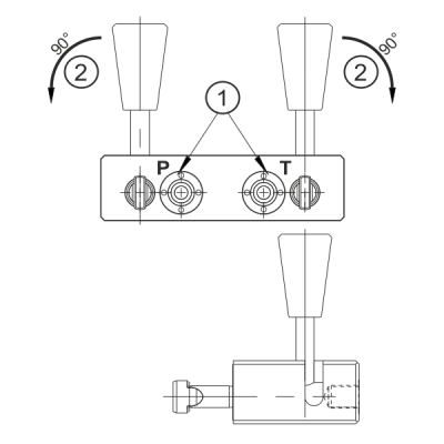
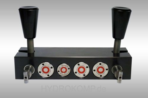
The coupling mechanism unit is used to lock both assemblies for pressure transmission. The two tie rods are inserted into the bayonet catch. The levers are then turned sideways by 90°. The tie rods are shortened via the two integrated molded bevels and the coupling process is carried out. The locking stroke is 5 mm.

1. coupling mechanisms
2. hand lever for locking the assemblies

010002_Aufbauzeichnung_MKS-1
Safety holder with inductive proximity switch and plug for holding the coupling mechanism strip in a parking station when decoupled. The safety holder can be connected directly to the machine control system via the integrated proximity switch. This means that pallets can only be transported when uncoupled.

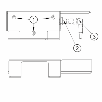
1. bore with countersink DIN 74 F4
2. inductive proximity switch
3. plug with cable

010002_Aufbauzeichnung_MK-1

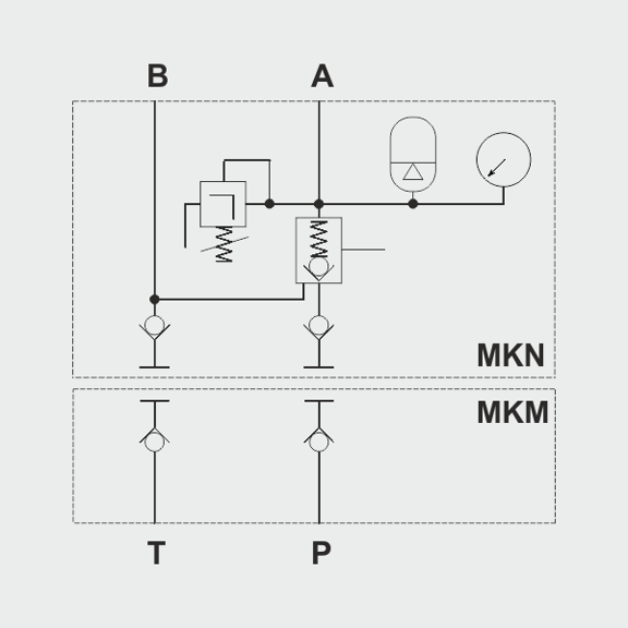
This coupling unit can be connected at the factory with either a bottom flange connection, rear flange connection or rear threaded connection.

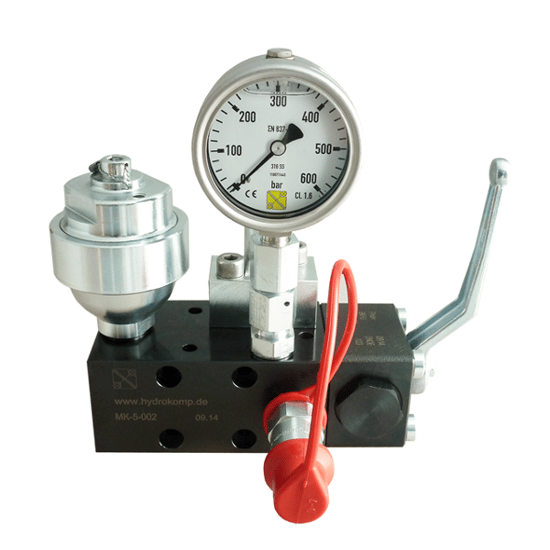
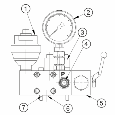
1. hydraulic accumulator 13 cm³ or 40 cm³ (optional)
2. pressure gauge up to 600 bar
3. pressure relief valve, opening pressure 425 bar
4. flat-face plug with dust protection cap
5. ball valve
6. connection Ø5 mm, O-ring or screw plug
7. cylinder head screws DIN 916

Practical examples

010002_Manual_coupling_unit_with_ball_valve

Manual coupling unit with ball valve ©

010002_Praxisbeispiel_MKM

Manual coupling bar with 4 coupling points

Configurator


Get started now and make a personal appointment!

We will be happy to advise you by telephone:
+49 (0) 6401 - 225 999-0

Or make an appointment with us.
Contact us