Hero_Tablet-Mobile_430-2_print translator

430-2 
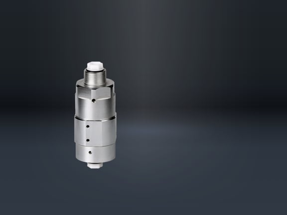
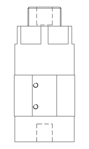
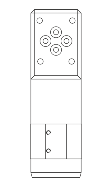
Pressure intensifier
hydraulic - hydraulic

These pressure intensifiers increase a hydraulic pressure in a fixed ratio.

Configure now Download data sheet

Info

These pressure intensifiers increase a hydraulic pressure in a fixed ratio. With this method, for example, machine hydraulics with a low pressure can be used for consumers that use a much higher pressure economically. The pressure intensification takes place via a fixed surface ratio of two piston surfaces. This allows the secondary pressure to be controlled via the inlet pressure. A bypass non-return valve is provided for rapid filling of the hydraulic consumers. The pressure intensification starts automatically at approx. 20 bar. The oscillating pumping process starts automatically when a volume flow passes through the pressure intensifier. The pressure intensification ends automatically when the consumer no longer requires a volume flow and the high pressure is reached. The volume flow on the high pressure side depends on the high pressure reached. The higher the high pressure reached, the lower the volume flow.

Operating conditions:
It is recommended that apressure filter with a maximum filter fineness of 10 µm is installed upstream of the low-pressure connection. Due to the design of these pressure intensifiers, an internal leakage occurs which is automatically discharged. For uncoupled consumers, it is recommended that an additional pilot-operatednon-return valve is fitted between the pressure booster and the consumer. This can be controlled to open via the T-line.

Special features:

  • Low-wear design
  • Wide range of connection options
  • Fast, low-loss pressure transmission
  • Integrated valve and filter functions possible
  • verschleißarme Bauweise
  • vielfältige Anschlussmöglichkeiten
  • schnelle verlustarme Druckübertragung
  • integrierte Ventil- und Filterfunktionen möglich
Connection types: G1/4 thread, O-ring flange or CETOP-NG-6
Mode of operation: Hydraulic-hydraulic
Operating temp: from -40 °C to +120° C
Medium: Hydraulic oil up to max. HLP 40, HFC fluid with min. 5% glycol content

Variants

043002_Sketch_1

Variants with transmission ratio
1,5 : 1
2,0 : 1
3,4 : 1
4,0 : 1
5,0 : 1
Max. volume flow high pressure, start - end
0,8 - 0,2
2,2 - 0,5
1,8 - 0,4
1,4 - 0,3
Max. operating pressure inlet low pressure
160 / 200 bar
max. operating pressure outlet high pressure
300 / 400 / 680 / 800 bar

043002_Sketch_2
Variants with transmission ratio
2,0 : 1
3,4 : 1
4,0 : 1
5,0 : 1
7,0 : 1
Max. volume flow high pressure, start - end
0,8 - 0,2
2,2 - 0,5
1,8 - 0,4
1,4 - 0,3
1,1 - 0,2
Max. operating pressure inlet low pressure
100 / 140 / 175 / 200 bar
max. operating pressure outlet high pressure
400 / 680 / 700 bar

043002_Sketch_3

Variants with transmission ratio
1,5 : 1
2,0 : 1
3,4 : 1
4,0 : 1
5,0 : 1
7,0 : 1
9,0 : 1
Max. volume flow high pressure, start - end
0,8 - 0,2
2,2 - 0,5
1,8 - 0,4
1,4 - 0,3
1,1 - 0,2
0,7 - 0,1
Max. operating pressure inlet low pressure
56 / 71 / 100 / 125 / 147 / 200 bar
Max. operating pressure outlet high pressure
300 / 400 / 500 bar

Configurator


Get started now and make a personal appointment!

We will be happy to advise you by telephone:
+49 (0) 6401 - 225 999-0

Or make an appointment with us.
Contact us