In intermittent applications, the connected pressure generator fills the hydraulic accumulator during interruptions. This creates a high volume flow for a short time, which can be used by the pressure generator as required to save drive power. As volume accumulators, hydraulic accumulators are also suitable as a source of pressure oil for emergency actuation in the event of failure of the pump-side pressure oil supply. When using hydraulic accumulators, the system must be equipped with additional safety elements (see safety instructions below). All work on the hydraulic accumulator may only be carried out by authorized persons.
Areas of application:
Compensate for system-internal leaks!
In hydraulic clamping systems, the pressure generators generally work in shut-off mode. A pressure switch controls the switching operations of the drive motor. If elements are connected in the system that cause leakage due to their design, e.g. controlled rotary feedthroughs, this causes frequent switching operations. The hydraulic accumulator significantly reduces the number of times the drive motor is switched on and off. This saves energy and reduces material wear.
Compensate for volume changes!
Temperature fluctuations can occur with uncoupled clamping systems. These inevitably lead to considerable changes in the clamping pressure (± 10 bar at ± 1° C). The installation of a hydraulic accumulator in the system creates a volume compensation and thus prevents the undesirable pressure fluctuations.
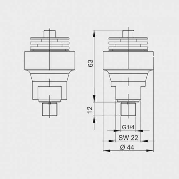
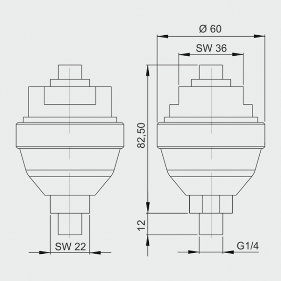
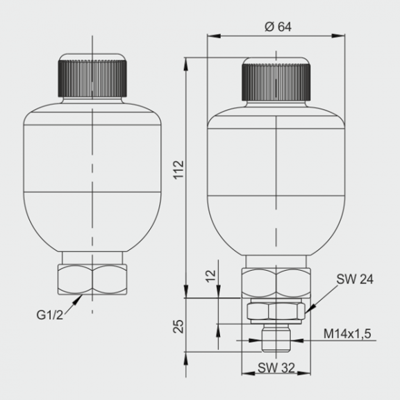
Mode of operation:
The diaphragm is pressurized with nitrogen. The integrated valve disk closes the opening for the oil inlet. This prevents damage to the diaphragm. At minimum operating pressure, a small amount of pressurized oil must remain in the
so that the diaphragm does not close the oil inlet due to the pressure on the valve disk during emptying.
p0 must therefore always be set lower than p1. The amount of fluid stored corresponds to the change in volume ΔV between the position at minimum and maximum operating pressure.
Safety note:
Hydraulic accumulators are subject to the TRB (Technical Rules for Pressure Vessels) regulations in Germany. Accordingly, the following additional equipment is required when using hydraulic accumulators
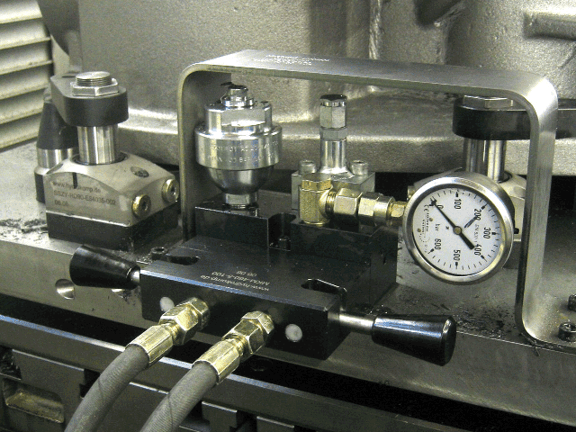
- Pressure gauge
- Pressure relief device
- Pressure relief valve
- Shut-off valve (optional)
- Test pressure gauge connection
Outside Germany, the national regulations and ordinances for the use of pressure vessels in the respective country apply.